


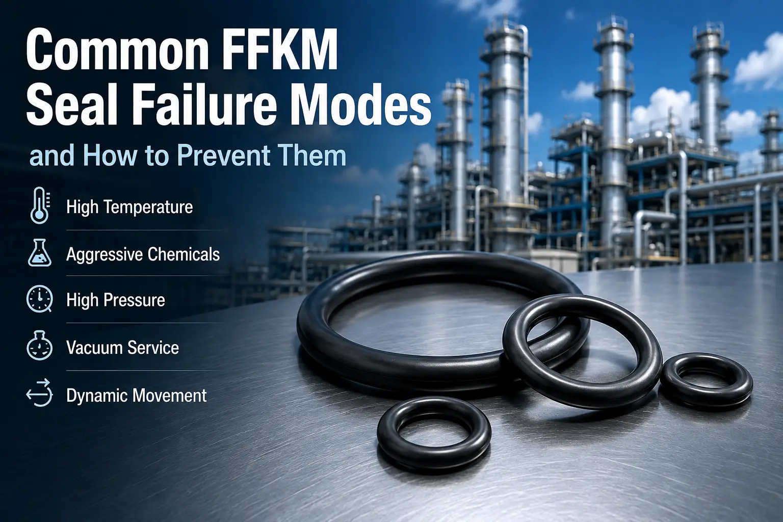
Common FFKM Seal Failure Modes and How to Prevent Them
Identify what the damaged seal is telling you—then connect the symptom to chemistry, temperature, pressure, groove design and installation before selecting another compound.
FFKM seals are selected for demanding chemical processing, semiconductor, pharmaceutical, vacuum, oil and gas, and high-temperature equipment. Their broad chemical resistance and thermal capability make them one of the most advanced elastomer families available—but FFKM is not failure-proof.
An expensive FFKM O-ring can still fail when the wrong compound is selected, the media is incompatible, groove dimensions are incorrect, pressure drives extrusion, temperature exceeds the real limit, installation damages the seal, dynamic wear is underestimated or high-pressure gas decompresses too quickly.
FFKM seal reliability depends on selecting the right compound and designing the complete sealing system around the real chemical, temperature, pressure and mechanical conditions.
START WITH THE EVIDENCE
Quick FFKM Failure Diagnosis
A damaged seal should always be inspected before replacement. Select the most obvious symptom for a first-pass diagnosis, then verify it against the operating history and groove.
What does the failed seal look like?
Preserve the seal and select a symptom.
The damaged component, service history and groove dimensions should be reviewed together before another seal is installed.
Photograph the seal, record the duty and compare it with an unused part.
Screening aid only. Several mechanisms can produce similar damage, and one failure can trigger another.
| Failure symptom | Likely cause |
|---|---|
| Seal becomes permanently flat | Compression set |
| Seal swells or becomes soft | Chemical incompatibility |
| Seal becomes hard or brittle | Excessive temperature or chemical aging |
| Torn or nibbled edges | Extrusion |
| Internal cracks or blisters | Rapid gas decompression |
| Cracks after cold startup | Low-temperature embrittlement |
| Cuts or scratches | Installation damage |
| Polished or worn sealing surface | Dynamic abrasion |
| Seal sticks to hardware | Heat, chemical exposure or excessive compression |
| Leakage after shutdown | Loss of sealing force |
| Particles around seal | Wear, plasma attack or surface degradation |
| Failure soon after a material change | Incorrect compound or groove design |
Simply installing another FFKM O-ring without identifying the root cause often produces the same failure again.
LOSS OF RECOVERY
Compression Set
Compression set is one of the most common causes of long-term elastomer leakage. An O-ring seals because it is compressed between two surfaces and continually tries to recover. Heat and chemical exposure can reduce that recovery until the cross-section remains permanently flattened.
Typical symptoms
- Flattened cross-section
- Loss of round shape
- Leakage after long service or cooling
- Poor sealing after restart
- Reduced vacuum performance
Common causes
- Excessive operating temperature
- Long-term static compression
- Incorrect compound selection
- Excessive groove squeeze
- Chemical degradation
- Repeated thermal cycling
Protect seal-force retention
- Match continuous temperature
- Verify groove compression
- Include operating duration
- Review chemistry and cycling
- Use long-term force data for critical service
VOLUME AND PROPERTY CHANGE
Chemical Swelling and Chemical Attack
FFKM provides extremely broad chemical resistance, but no compound should be assumed to resist every fluid at every temperature. Incompatibility can swell, soften, harden, shrink or crack the seal and reduce its tensile strength.
Signs of attack
- Increased diameter or cross-section
- Soft or sticky surface
- Difficult groove removal
- Excessive friction
- Extrusion damage
Common causes
- Incorrect FFKM compound
- Higher concentration than expected
- Unexpected contaminants
- Cleaning chemicals
- Elevated temperature
- Mixed chemical streams
Specify the real media
- Exact chemical names
- Concentrations and water content
- Operating temperature and duration
- Cleaning media
- Actual-fluid immersion testing for critical duty
Do not specify only “acid,” “solvent” or “amine.” Compatibility depends on the exact chemical, concentration, mixture, temperature and exposure time.
REAL DUTY CYCLE
Excessive Temperature and Thermal Degradation
Every FFKM formulation has thermal limits. Some specialized compounds can operate above 300°C, while others are optimized for lower-temperature wet chemistry. Applying one generic maximum temperature to every FFKM compound is a common mistake.
Thermal symptoms
- Hardening and cracking
- Surface glazing
- Loss of elasticity
- Compression set
- Permanent deformation
- Discoloration
Peak vs continuous
- Normal operating temperature
- Maximum continuous temperature
- Peak temperature and duration
- Cleaning temperature
- Sterilization temperature
Qualify every cycle
- Provide minimum through peak values
- Record heating and cooling cycles
- Treat repeated peaks as normal duty
- Check elasticity and force retention
PRESSURE + CLEARANCE
Extrusion and Nibbling
Extrusion occurs when pressure pushes the FFKM seal into the clearance between mating components. Once material enters the gap, repeated pressure cycles can cut or tear it.
Typical symptoms
- Nibbled edges
- Torn material
- Small missing pieces
- Low-pressure-side damage
- Sudden leakage
Common causes
- Excessive pressure
- Large hardware clearance
- High temperature
- Soft compound
- Chemical swelling
- Incorrect groove dimensions
Support the seal
- Reduce extrusion clearance
- Review harder compounds
- Add backup rings
- Improve groove support
- Reduce pressure spikes
- Investigate swelling
The hardest compound is not automatically best. Seal hardness, pressure, temperature and gland geometry must be evaluated together.
FAILURE FROM THE INSIDE OUT
Rapid Gas Decompression Failure
During high-pressure gas service, gas can diffuse into the FFKM. If pressure drops too quickly, trapped gas expands inside the seal and creates internal cracks, blisters or explosive-looking fractures.
Gas diffuses into the elastomer.
Internal gas expands faster than it can escape.
RGD symptoms
- Internal cracks
- Blisters and bubbles
- Splitting
- Inside-out fractures
Common applications
- Natural gas and hydrogen
- CO₂ systems
- Oil and gas valves
- High-pressure compressors
- Downhole equipment
Control material and process
- Use an RGD-tested compound
- Control decompression rate
- Define pressure and gas composition
- Include temperature and cross-section
General chemical resistance does not mean a compound is resistant to rapid gas decompression.
RECOVERY AT STARTUP
Low-Temperature Failure
FFKM is better known for heat resistance than extreme low-temperature flexibility. As temperature falls, recovery becomes slower and the material may not respond quickly enough to movement or pressure changes.
Typical symptoms
- Cold-start leakage
- Temporary leakage before warm-up
- Cracking
- Loss of sealing force
- Leaks during rapid pressure change
Relevant data
- Minimum startup temperature
- TR10
- Glass-transition behavior
- Static vs dynamic service
- Actual leakage tests
Use a cold-service grade
- Qualify at actual startup conditions
- Test pressure and movement response
- Balance low and high temperature needs
- Consider alternative seal technology
DAMAGE BEFORE SERVICE
Installation Damage
FFKM seals can be cut, scratched, twisted, overstretched or pinched during installation. A small defect may remain invisible until pressure is applied.
Damage patterns
- Cuts and scratches
- Twisting
- Overstretching
- Pinching
- Sharp-edge marks
Where damage occurs
- Threads and keyways
- Sharp shoulders
- Ports
- Machining burrs
- Improper tools
Control installation
- Use proper tools and sleeves
- Provide lead-in chamfers
- Use approved lubricant
- Keep hardware clean
- Avoid excessive stretch
- Inspect after installation
SIZE CHANGES UNDER TENSION
Excessive O-Ring Stretch
Moderate stretch is normal in some applications, but excessive stretch reduces the O-ring cross-section and changes compression inside the groove. Large-diameter FFKM seals make incorrect sizing especially costly.
- Reduced sealing contact
- Higher material stress
- Shorter service life
- More thermal-cycle sensitivity
- Verify O-ring inside diameter
- Check groove diameter
- Calculate percentage stretch
- Confirm final cross-section
- Include hardware tolerance
- Use a custom size when necessary
MORE SQUEEZE IS NOT ALWAYS BETTER
Excessive Compression
Excessive squeeze raises internal stress, heat generation, compression set, groove fill and extrusion risk. Chemical swelling and thermal expansion make the problem more severe.
- High internal stress
- Heat generation
- Accelerated compression set
- Excessive groove fill
- Extrusion
- O-ring volume
- Thermal expansion
- Chemical swelling
- Manufacturing tolerances
- Real compound behavior
FRICTION OVER TIME
Dynamic Wear and Abrasion
Reciprocating rods, valve stems, pistons and rotating equipment introduce friction and wear. Dynamic suitability depends on the entire interface—not chemical resistance alone.
Signs of wear
- Flattened contact surface
- Polished areas
- Grooves
- Material loss
- Particles
- Progressive leakage
Common causes
- Rough hardware surface
- High speed
- Insufficient lubrication
- Excessive squeeze
- Side loading
- Poor alignment
Engineer the interface
- Review surface finish and shaft hardness
- Define speed and lubrication
- Match seal hardness
- Check alignment and groove geometry
- Compare energized PTFE for high speed
For very low friction or high-speed motion, a spring energized PTFE seal may be a better solution than an FFKM O-ring.
ROLLING INSTEAD OF SLIDING
Spiral Failure
In reciprocating service, an O-ring may roll or twist in the groove instead of sliding uniformly. Repeated torsion creates a distinctive spiral damage pattern.
Typical symptoms
- Spiral cuts
- Twisted surface
- Diagonal wear patterns
- Repeated tearing
Possible causes
- Uneven friction
- Poor lubrication
- Excessive groove clearance
- Side loading
- Long stroke movement
Stop the rolling action
- Improve lubrication
- Correct alignment
- Optimize surface finish
- Review groove design
- Use a dynamic seal profile for severe duty
FAILURE BEFORE LEAKAGE
Plasma Erosion in Semiconductor Equipment
Reactive radicals and energetic ions can attack an FFKM surface, causing roughness, weight loss, cracks, particles, filler exposure and loss of sealing force. Oxygen, fluorine and chlorine plasma can produce different degradation mechanisms.
Plasma symptoms
- Surface roughness
- Weight loss
- Cracking
- Particle generation
- Filler exposure
- Loss of sealing force
Contamination risks
- Particles
- Trace metals
- Volatile compounds
- Chamber cleanliness loss
- Wafer-yield impact
Match the chamber duty
- Plasma chemistry and RF power
- Pressure and seal location
- Temperature
- Particle requirements
- Outgassing requirements
HEAT + WATER + PRESSURE
Steam and Hot-Water Degradation
A high-temperature FFKM is not automatically suitable for steam. Some grades are formulated for steam and hot-water resistance, while others are designed mainly for dry heat.
- Swelling
- Softening
- Surface damage
- Loss of sealing force
- Leakage after repeated SIP cycles
- Use a steam-recommended compound
- Provide steam pressure and temperature
- Define cycle duration and count
- Include cleaning chemicals
- Validate hot water, CIP and SIP together
CHEMISTRY AT TEMPERATURE
Hot Amine Attack
Amines can be demanding for FFKM, particularly at elevated temperatures in gas sweetening, refining, carbon capture, chemical production and pharmaceutical processing.
- Swelling or softening
- Hardening
- Compression set
- Loss of strength
- Specify the exact amine
- Provide concentration
- Include water content
- Define temperature and pressure
- Use an amine-resistant formulation
The highest-temperature FFKM is not automatically the best amine-resistant material.
CONTAINMENT AT LOW PRESSURE
Vacuum Leakage
FFKM is widely used in vacuum equipment, but compression set, contamination, groove error, damage, permeation, outgassing or poor low-temperature recovery can still prevent the system from reaching stable base pressure.
Vacuum behavior
- Longer pump-down time
- Difficulty reaching base pressure
- Pressure instability
- Leakage after cooldown
Possible causes
- Compression set
- Surface contamination
- Incorrect groove design
- Seal damage
- Permeation and outgassing
- Low-temperature recovery loss
Review the vacuum interface
- Seal squeeze and surface finish
- Compression set
- Outgassing and permeation
- Bake-out temperature
- Purity and particles
FFKM IS A MATERIAL FAMILY
Wrong FFKM Compound Selection
Different FFKM formulations are optimized for different failure risks. A compound selected only because it is “FFKM” may perform poorly in a specific application.
Leaves too much performance variation for critical equipment.
Identifies the performance, certification and validation actually required.
Do not specify only “Material: FFKM.” Identify the exact compound, hardness, seal size, certification and test requirements.
PRESERVE · DOCUMENT · COMPARE
A Practical FFKM Failure Analysis Process
The failed seal contains valuable evidence. Follow a consistent process before cleaning, discarding or replacing it.
Record the failure condition
Document service time, temperature, pressure, process media, cleaning cycle, failure date and recent process changes.
Photograph the seal
Capture the seal before removal, inside the groove, after removal and from multiple angles.
Inspect the failure pattern
Look for swelling, flattening, cuts, cracks, extrusion, blisters and wear.
Measure the seal
Compare inside diameter, cross-section, hardness and weight with an unused seal whenever possible.
Review the groove
Check groove width, depth, extrusion clearance, surface finish and sharp edges.
Review operating conditions
Ask whether temperature, concentration, pressure, cleaning agent or maintenance procedure changed.
Identify the root cause
Separate hardware, installation, pressure, chemical exposure and compound-selection causes before approving corrective action.
Do not clean the evidence away before photographs, dimensions and the as-found groove condition have been recorded.
QUALIFY BEFORE APPROVAL
FFKM Failure Prevention Checklist
Confirm the complete duty before approving a compound, size or seal design. Missing one process condition can invalidate an otherwise careful selection.
Media
- Complete chemical list
- Concentrations
- Cleaning chemicals
- Process gases
Temperature
- Minimum
- Normal
- Maximum continuous
- Peak and duration
Pressure
- Normal
- Maximum
- Vacuum
- Decompression rate
Movement
- Static
- Reciprocating
- Rotary
- Speed and cycles
Seal design
- Groove dimensions
- Squeeze
- Stretch
- Extrusion gap
Performance
- Required service life
- Maintenance interval
- Leakage requirement
- Failure consequences
Special conditions
- Steam
- Hot amines
- Plasma
- High-pressure gas
- Semiconductor purity
- Cleaning and sterilization
MATERIAL CORRECTION
When Should You Change the FFKM Compound?
Change the compound when the evidence points to a formulation-performance gap. Do not use a material change to hide hardware or installation problems.
- The seal swells chemically
- Compression set is excessive
- Low-temperature leakage occurs
- Steam causes degradation
- Amine exposure shortens life
- Plasma produces particles
- High-pressure gas causes RGD
CAUSE
- Cuts
- Incorrect groove dimensions
- Excessive clearance
- Poor surface finish
- Installation damage
- Hardware misalignment
These require a design, hardware or installation correction.
GEOMETRY CORRECTION
When Should You Change the Seal Design?
A profile or support change may be more effective when pressure and motion dominate the failure. The best solution can combine a more suitable material with a more suitable geometry.
- Extrusion
- Excessive dynamic wear
- High friction
- O-ring twisting
- Extreme pressure
- High rotary speed
SYSTEM-LEVEL RELIABILITY
Engineering Summary
FFKM provides exceptional chemical and temperature resistance, but reliable sealing still requires correct engineering. The most expensive compound cannot compensate for an incorrect groove or incomplete application data.
For critical equipment, base the failure analysis on the actual damaged seal, operating history and groove geometry before selecting a replacement material.
TECHNICAL ANSWERS
Frequently Asked Questions
FFKM seals usually fail because of incorrect compound selection, excessive temperature, chemical incompatibility, extrusion, compression set, installation damage or an unsuitable groove design.
Yes. Although FFKM has broad chemical resistance, an incompatible chemical, mixture or severe temperature can still cause swelling.
Permanent flattening usually indicates compression set and loss of elastic recovery, which reduces sealing contact force.
Cracking can be caused by heat aging, chemical attack, low-temperature stress, plasma exposure or rapid gas decompression.
Yes. Not every FFKM compound is designed for steam. Select a steam-resistant grade for hot-water, CIP and SIP applications.
Yes. Rapid decompression can cause internal cracks and blisters unless an RGD-resistant compound and a controlled decompression process are used.
High pressure, excessive hardware clearance, high temperature, soft compounds and chemical swelling can all contribute to extrusion.
Not automatically. A harder compound will not correct chemical incompatibility, incorrect groove dimensions, installation damage or poor hardware alignment.
Look for swelling, softening, hardening, shrinkage or a major dimensional change compared with an unused seal, then verify the actual media and temperature.
No. FFKM can improve chemical and temperature resistance, but pressure, friction, hardware design, groove dimensions and installation must still be correct.
Turn the damaged seal into a reliable corrective action.
Walle Seals supplies custom FFKM O-rings, gaskets and molded components for chemical, semiconductor, pharmaceutical, vacuum, oil and gas, and high-temperature equipment.
Discuss your failure analysis →- Failed-seal photographs
- Chemicals and concentrations
- Operating temperature
- Pressure or vacuum
- Seal dimensions
- Groove drawing
- Current compound
- Service life and symptoms
Our engineering team can help identify the likely mechanism and recommend a suitable compound or seal design.
No responses yet